Interface overview and connections – inverter
Inverter:
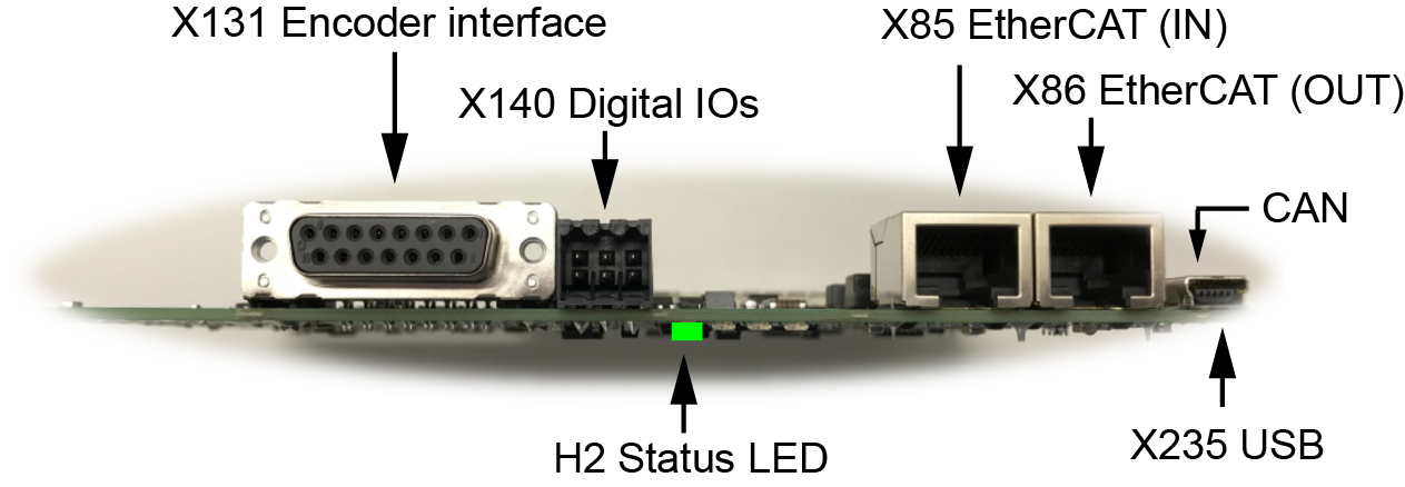
Controller card:
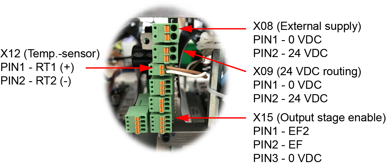
Supply and logic board:
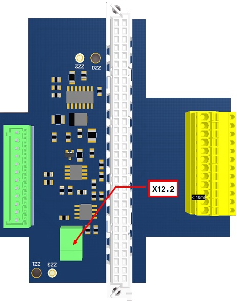
Transverse board terminal X12_2
|
Interfaces |
Number |
Function |
|---|---|---|
| X08 / X09 |
2 |
Input for 24 VDC external supply (on-board supply) / 24 VDC routing 1) |
| X12 | 4 |
Motor temperature monitoring |
| X13 | 2 | Reserved |
| X14 | 2 | Reserved |
| X15 | 2 |
Output stage enable 1) |
| X16 | 2 | Reserved |
|
X85 |
4 |
Ethernet IN (EtherCAT) real time (connection to PC for AMK AIPEX PRO software (startup, diagnosis, and configuration) and ATF (firmware update) |
| X86 | 4 | Reserved |
|
X131 |
4 |
Motor encoder P encoder input, EnDat 2.1 (digital) |
|
X140 |
4 |
Binary IOs (2 inputs, 1 output) |
| X235 | 4 |
USB (connection to PC for AMK AIPEX PRO software (startup, diagnosis, and configuration) and ATF (firmware update) |
|
1) |
Common connection for I1 + I2 |
|
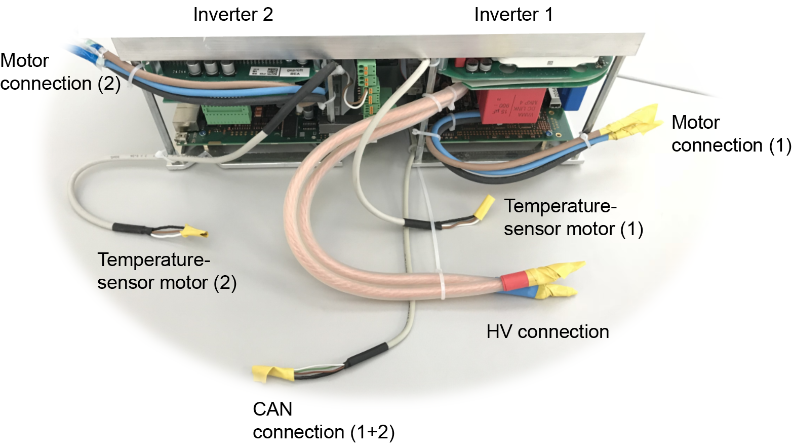
Interfaces |
Number |
Function |
|---|---|---|
| HV+ | 2 |
Battery connection + 1) |
| HV- | 2 |
Battery connection - 1) |
| U (brown) | 4 |
Motor phase U |
|
V (blue) |
4 |
Motor phase V |
| W (black) | 4 | Motor phase W |
| T-mot | 4 |
Motor temperature monitoring |
|
CAN bus |
2 |
CAN specification 2.0 A 1) |
|
1) |
Common connection for I1 + I2 |
Status LED H2
|
Class |
Status |
Note |
|---|---|---|
|
Drive status |
Green |
System Ready (SBM) |
|
Green flashing |
Drive under control (SBM and QRF) |
|
|
Orange flashing |
Warning occurs during active controller enable |
|
|
Orange |
Warning occurs during inactive controller enable / flash mode |
|
|
Red |
Error with reaction depending on the error number |
