Safe speed range (SSR)
Properties
- Safety function according to DIN EN 61800-5-2:2008-04
- Freely parameterisable safe speed range (2-channel actual speed value monitoring)
- 4 individually configurable safety functions SSR1, SSR2, SSR3, SSR4
- Parametrisable stop function in case of error
Description
The safety function is started by the corresponding bit in the control data.
The acknowledgement is fed back by status data.
The started SSR safety function monitors the speed change of the drive, and subsequently the operation within a parameterised safe speed range. The speed change must be initiated by the user controller.
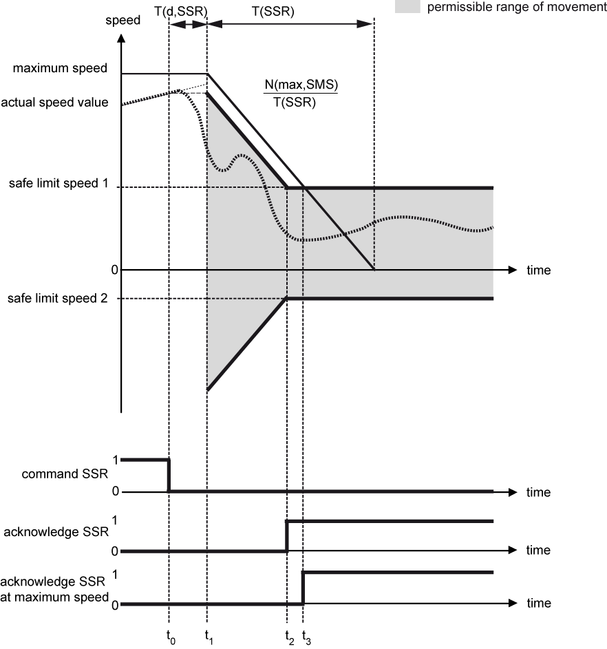
Example 1: Drive movement in the permissible range of movement
|
Time t |
Explanation |
|---|---|
|
t = t0
|
The safety function is started. |
|
t0 < t < t1 |
During the transition period, the actual speed value of the drive must be adjusted to the parameterised limits of the started safety function. The parameterised limits are not monitored yet. |
|
t1 ≤ t < t2 |
The safety function monitors the parameterised ramp and checks whether the actual speed value meets the permitted range of movement. |
|
t ≥ t2 |
The safety function switches the drive into the SSR state and sets the SSR acknowledgement bit. In the SSR state, the safety function monitors whether the actual speed value meets the parameterised safe speed range. |
|
t = t3 |
Acknowledgement SSR at maximum speed |
Reaction in case of an error
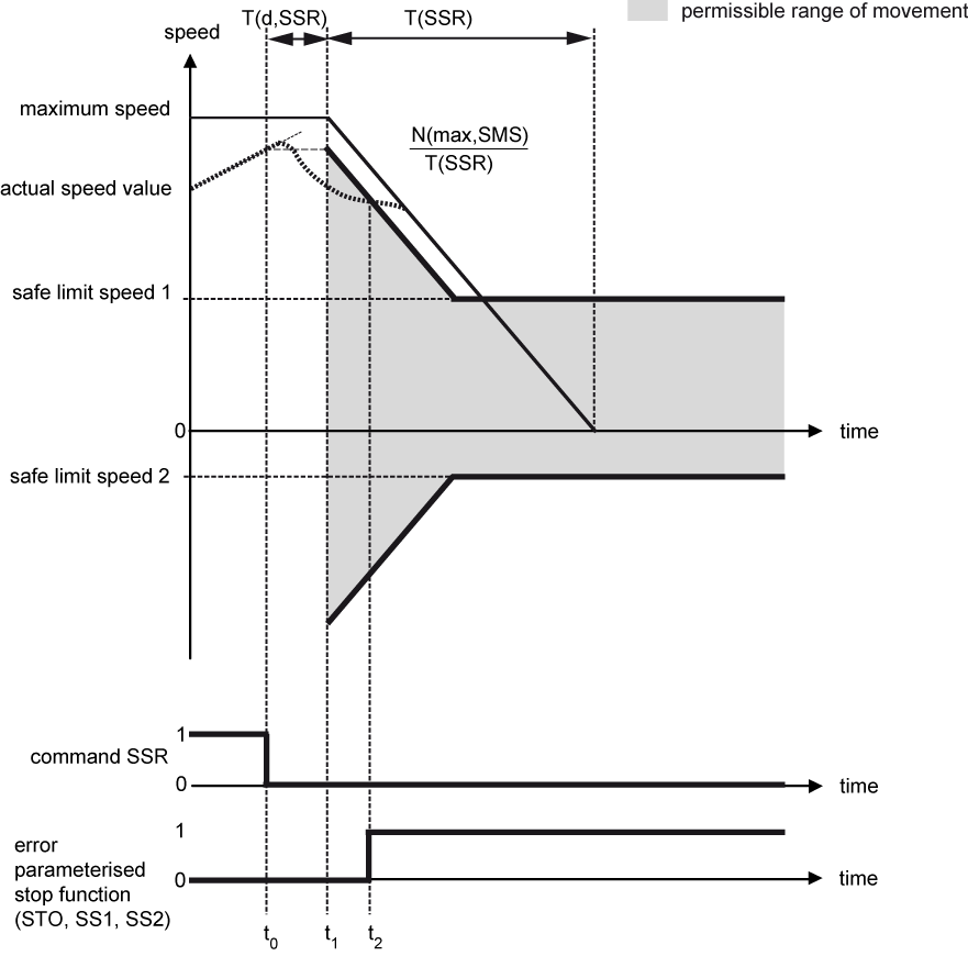
As soon as the safety function detects a deviation from the limits of the controlled values, the drive executes a safe stop function that has previously been set by parameter ('Safe torque off (STO)', 'Safe stop 1 (SS1)' or 'Safe stop 2 (SS2)') (example 2) and (example 2a).
The 4 SSR safety functions monitor the drive independently from each other. As soon as the drive leaves the speed range parameterised in one of the SSR1 - SSR4 safety functions, the stop function that has been parameterised for this SSR becomes active (example 3).
|
|
|
|
|
Danger to life due to unexpected movements! The drive will be torque-free in the status 'Safe torque off (STO)', in case of mains failure or in case of faulty drive controller. External application of force on the drive axis may result in life-threatening movements (e.g. hanging axes can fall down). Steps to prevent:
|


|
|
|
|
|
Danger due to unexpected stop function! If there are different error reactions projected for the safety functions, an unexpected final state can occur in case of error. Example: Steps to prevent:
|
|
|
The reaction time of the drive in case of error is prolonged by the reaction time of the parameterised stop function! |

Example 2: Drive movement deviates from the permissible range of movement
|
Time t |
Explanation |
|---|---|
| t = t0 |
The safety function is started. |
|
t0 < t < t1 |
During the transition period, the actual speed value of the drive must be adjusted to the parameterised limits of the started safety function. The parameterised limits are not monitored yet. |
|
t1 ≤ t < t2 |
The safety function monitors the parameterised ramp and checks whether the actual speed value meets the permissible range of movement. |
|
t = t2 |
The safety function detects an error, starts the parameterised stop function and sets the error bit. |
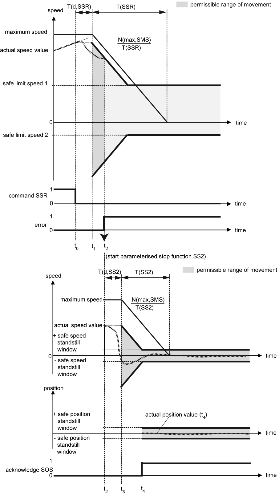
Example 2a: Drive movement deviates from the permissible range of movement (SS2 as parameterised stop function)
|
Time t |
Explanation |
|---|---|
|
t = t0
|
The safety function is started. |
|
t0 < t < t1 |
In the transition period, the actual speed value of the drive must be adjusted to the parameterised limits of the started safety function. The parameterised limits are not monitored yet. |
|
t1 ≤ t < t2 |
The safety function monitors the parameterised ramp and checks whether the actual speed value lies within the permissible range of movement. |
|
t = t2 |
The safety function detects an error, starts the parameterised stop function SS2 and sets the error bit. |
|
t2 < t < t3 |
In the transition period, the actual speed value of the drive must be adjusted to the parameterised limits of the started safety function. The parameterised limits are not monitored yet. |
|
t3 ≤ t < t4 |
The safety function monitors the parameterised ramp and checks whether the actual speed value lies within the permissible range of movement. |
|
t ≥ t4 |
The safety function switches the drive into the SOS state and sets the SOS acknowledgement bit. |
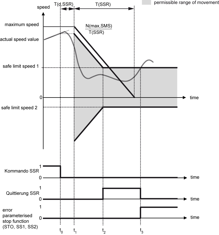
Example 3: Drive movement deviates from the safe speed range in the SSR state
|
Time t |
Explanation |
|---|---|
|
t = t0 |
The safety function is started. |
|
t0 < t < t1 |
During the transition period, the actual speed value of the drive must be adjusted to the parameterised limits of the started safety function. The parameterised limits are not monitored yet. |
|
t1 ≤ t < t2 |
The safety function monitors the parameterised ramp and checks whether the actual speed value lies within the permissible range of movement. |
|
t = t2 |
The safety function switches the drive into the SSR state and sets the SSR acknowledgement bit. |
|
t2 ≤ t < t3 |
In the SSR state, the safety function monitors whether the actual speed value meets the safe speed range. |
|
t = t3 |
The safety function detects an error, switches the drive into the parameterised stop function and sets the error bit. The SSR acknowledgement bit is reset. |
|
t ≥ t3 |
The drive behaviour depends on the parametrised stop function. |
Acknowledge an error with "Clear error"
As soon as an active safety function detects a deviation from the limits of the monitored values, the drive is set to the intended stop function. The error bit (FSoE status bit 7) is set and the acknowledgment of the safe status is withdrawn.
With the 'Clear error' signal (FSoE control bit 7 or the 'Clear error' command in the drive controller) the
error status ist acknowledged (deleted). If during and after the 'Clear error' the start signal from a previous safety function is still active and no other changes to the settings of the safety function have been made, the safety function restarts and also transition times (if available) work again.
Parameters
Safe parameters
|
Parameter |
Name |
Code |
Unit |
Min |
Max |
|
'SSR1 transition period' |
T(d,SSR1) |
ms |
0 |
65535 |
|
'SSR1 brake ramp time' |
T(SSR1) |
ms |
0 |
65535 |
|
'SSR1 safe limit speed 1' |
N(ul,SSR1) |
rpm |
-60000 |
60000 |
|
'SSR1 safe limit speed 2' |
N(ll,SSR1) |
rpm |
-60000 |
60000 |
|
'SSR1 error reaction' |
SSR1_ERR |
- |
0 |
2 |
|
'SSR2 transition period' |
T(d,SSR2) |
ms |
0 |
65535 |
|
'SSR2 brake ramp time' |
T(SSR2) |
ms |
0 |
65535 |
|
'SSR2 safe limit speed 1' |
N(ul,SSR2) |
rpm |
-60000 |
60000 |
|
'SSR2 safe limit speed 2' |
N(ll,SSR2) |
rpm |
-60000 |
60000 |
|
'SSR2 error reaction' |
SSR2_ERR |
- |
0 |
2 |
|
'SSR3 transition period' |
T(d,SSR3) |
ms |
0 |
65535 |
|
'SSR3 brake ramp time' |
T(SSR3) |
ms |
0 |
65535 |
|
'SSR3 safe limit speed 1' |
N(ul,SSR3) |
rpm |
-60000 |
60000 |
|
'SSR3 safe limit speed 2' |
N(ll,SSR3) |
rpm |
-60000 |
60000 |
|
'SSR3 error reaction' |
SSR3_ERR |
- |
0 |
2 |
|
'SSR4 transition period' |
T(d,SSR4) |
ms |
0 |
65535 |
|
'SSR4 brake ramp time' |
T(SSR4) |
ms |
0 |
65535 |
|
'SSR4 safe limit speed 1' |
N(ul,SSR4) |
rpm |
-60000 |
60000 |
|
'SSR4 safe limit speed 2' |
N(ll,SSR4) |
rpm |
-60000 |
60000 |
|
'SSR4 error reaction' |
SSR4_ERR |
- |
0 |
2 |
|
'SMS safe maximum speed' |
N(max,SMS) |
rpm |
0 |
60000 |
