Scope - Manual
You can conduct drive-specific or device-spanning measurements (only ACC bus).
For drive-specific measurements, mark a drive in the device tree.
For device-spanning measurements, mark the fieldbus (ACC bus). You can then record and display the signals of several devices. The measurement is started on all drives by a common trigger signal.
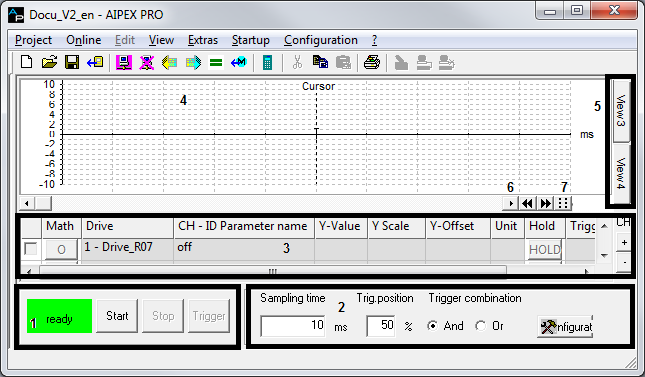
|
Number |
Function |
|---|---|
|
1 |
Operating the oscilloscope (Start, Stop and Trigger button) Status display Offline (grey) Ready (green) Started (yellow) Triggered (yellow) Ready (green) Error (red) |
|
2 |
Configuration field |
|
3 |
Field for drive selection and signal parameters |
|
4 |
Display |
|
5 |
Each view has an own channel selection |
|
6 |
Scaling the time axis |
|
7 |
Grid in the display (on / off) |
|
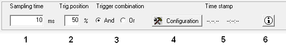
Number |
Function |
|---|---|
|
1 |
Input field for the scan period of the following measurements (device specific) |
|
2 |
Trigger position. (The characteristic curve can be displayed before the trigger event ("pre trigger"). |
|
3 |
If multiple trigger signals are used, you can select between an "and" or an "or" link of the trigger signals. |
|
4 |
Button for opening the configuration field |
|
5 |
Display of the date and the time after a measurement |
|
6 |
Button for opening and entering information about the measurement (a yellow button indicates that text information is available) |
|
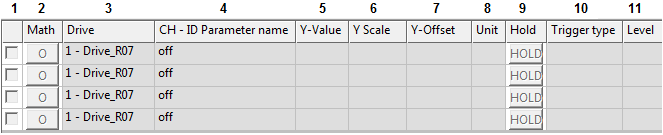
Number |
Function |
|---|---|
|
1 |
Control box for displaying the signal curve |
|
2 |
Computation of signals (addition, subtraction...) |
| 3 | Drive name |
|
4 |
Channel display: Signal (parameter number and name) of the selected channel |
|
5 |
Display of actual value |
|
6 |
Input box Y- Scale |
| 7 | Input box Y- Offset |
| 8 | Unit |
| 9 |
A 'HOLD' curve is not overwritten by a subsequent measurement. 'LET' delete saved measurement |
|
10 |
Configured trigger type |
| 11 | Configured level |
Status indicators

Status display "grey" – no valid device is selected or work is being done offline.
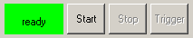
Status "ready" – oscilloscope is ready for start.
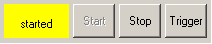
Status "started" – configuration of the channels is valid, oscilloscope started. The current values are shown.
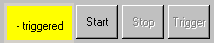
Status "triggered" – trigger fulfilled, or manually activated with the "Trigger" button. The data is retrieved from the drive.
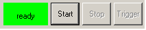
Status "ready" – measurement is complete and the curves are recorded.
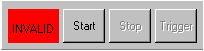
Status "INVALID" – configuration of the channels is invalid.
The oscilloscope does not support a signal on a configured channel, i.e. this signal is to be corrected or otherwise deactivated.
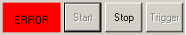
Status "ERROR" – can be an triggered by an error in the oscilloscope as well as a different error. The exact cause can be determined with the AIPEX PRO tab 'Diagnostics'.
