EtherCAT Cross Communication between two AMK controllers
The example shows how to exchange data between AMK controllers (writing and reading).
The PLC program of the PLC_Master controller sends an integer variable which is received from the PLC program of the PLC_Slave_02 controller.
Preparation
|
|
Required wiring and configuration of the controllers: See Product Description Controllers A4 / A5 / A6 section: 'Cross communication'
Creating an online project See Product Description Controllers A4 / A5 / A6 section: 'Cross communication' - Importing and configuring online project with AIPEX PRO'. |

Parameterization of controllers
In the cross communication between AMK controls the following parameters must be configured:
Use the function AIPEX PRO 'Direct Mode'
EtherCAT Master
|
Instance |
Parameter |
Value |
Meaning |
|---|---|---|---|
|
5
|
ID1204 'XML file' |
|
Bus configuration file |
|
ID1205 'XML file' |
|
Bus configuration file |
|
|
ID1206 'XML file' |
|
Bus configuration file |
|
|
ID1207 'XML file' |
|
Bus configuration file |
|
|
ID34023 'BUS address participant' |
0xFF |
Default address, can be assigned in the bus system only once |
|
|
ID34024 'BUS transmit rate' |
100.000 |
By default, equivalent to 100 Mbps, |
|
|
ID34025 'BUS mode' |
0x2 |
Master |
|
|
ID34026 'BUS mode attribute' |
0x0 |
- |
|
|
ID34140 'AS BUS protocol' |
0x41 |
EtherCAT Master / Slave |
|
|
ID34143 'Usage port' |
0x2 |
CC bus (cross communication between controllers) |
EtherCAT Slave
|
Instance |
Parameter |
Value |
Meaning |
|---|---|---|---|
|
2
|
ID34023 'BUS address participant' |
0 |
Default address, automatic addressing |
|
ID34024 'BUS transmit rate' |
100.000 |
By default, equivalent to 100 Mbps, |
|
|
ID34025 'BUS mode' |
0 |
Slave |
|
|
ID34026 'BUS mode attribute' |
0 |
- |
|
| ID34140 'AS BUS protocol' | 0x41 |
EtherCAT slave option A-SEC |
|
|
ID34143 'Usage port' |
2 |
CC bus (cross communication between controllers) |
|
|
The run up of the cross communication must be completed faster than the drive field bus. If needed you can use at the drive field bus master a run up delay time via ID34026 'BUS mode attribute'. |
After parameterization, both (all) controllers must be restarted (24 VDC OFF / ON)
After restarting the cross communication is active. The ACC master is connected via the ACC (CC) connection with the ACC slave.
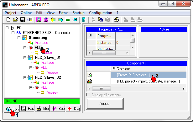
Read a configuration and save the project: AIPEX PRO 'Online' menu → 'Login'
Save the project: AIPEX PRO menu 'Project' → 'Save as...'
PLC Program Master Controller
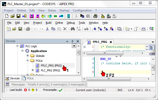
Create and save the PLC program for the PLC_Master controller.
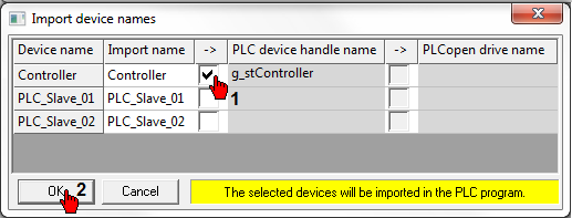
Transfer the 'PLC device handle name' (symbolic device name) of the PLC_Master controller to the PLC program.
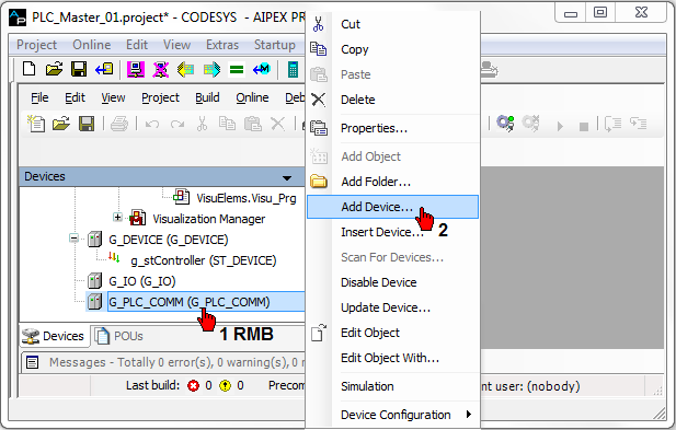
Change to the 'Controller configuration'.
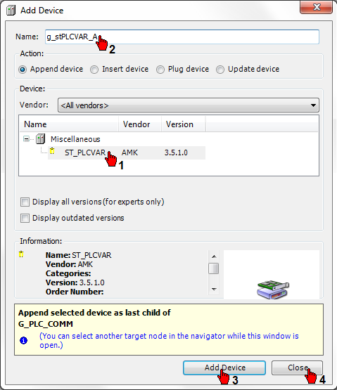
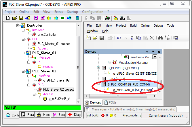
Add a communication variable of type ST_PLCVAR to the controller configuration G_PLC_COMM (g_stPLCVAR_A).
Create a communication variable (in the example g_stPLCVAR_A).
Add the PLC writing module (in the example, an integer variable in the synchronous level is transferred).
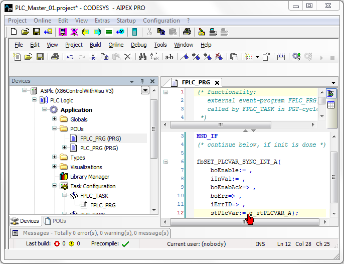
Instantiate in the real-time task FPLC_PRG a function block type SET_PLCVAR_SYNC_INT.
PLC function blocks for communication exchange between the controllers are provided with the 'AmkDevAccess' AMK library.
See asynchronous data exchange: Folder: 'POUs' → 'PlcVarAccess' → 'Asynchronous'
See synchronous data exchange: Folder: 'POUs' → 'PlcVarAccess' → 'Synchronous'
Function block SET_: write
Function block GET_: read
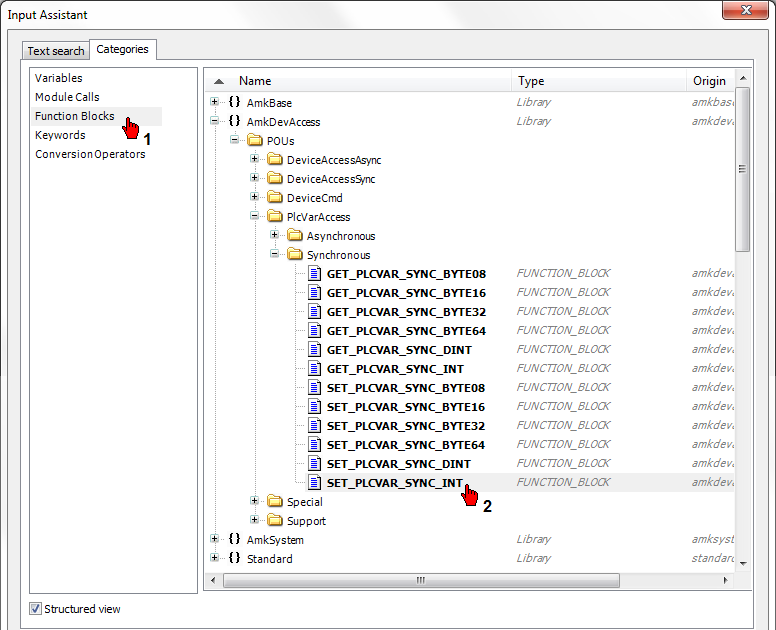
You can instantiate the function block by assigning its own name to it.
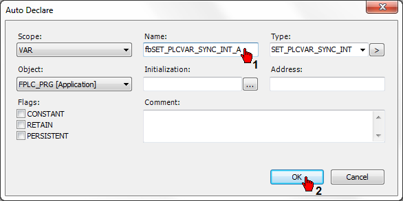
Link the function block variable 'stPlcVar' with the communication variable (g_stPLCVAR_A).
Create message configuration for the EtherCAT master
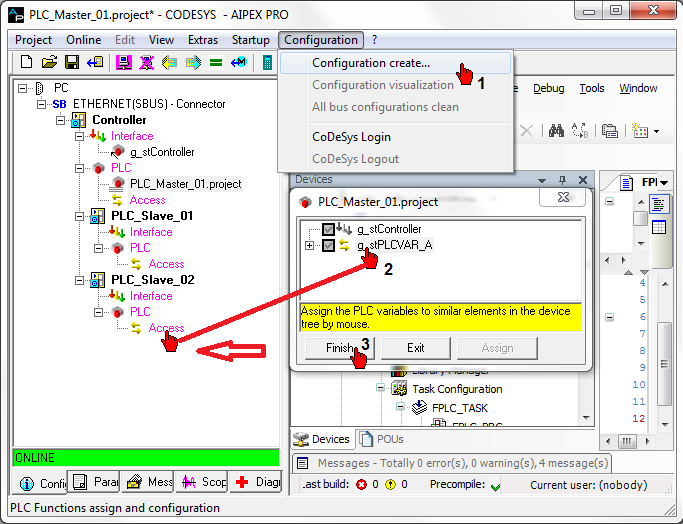
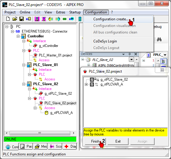
Click the AIPEX PRO menu 'Configuration ...' → 'Configuration create'
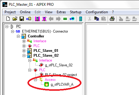
Assign the communication variable via 'drag and drop' to the EtherCAT slave (interface 'access')
|
|
The final variable mapping takes place after the slave PLC is programmed and the 'Configuration create' function is called. |
Communication settings
Siehe 'Creating PLC program and message configuration'.
Communication settings section
PLC Program Slave Controller
Create and save the PLC program for the PLC_Slave_02 controller.
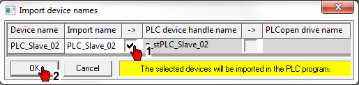
Transfer the 'PLC device handle name' (symbolic device name) of the PLC_Slave_02 controller to the PLC program.
|
|
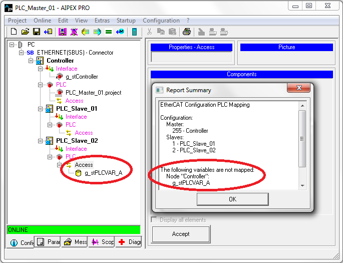
The assigned PLC communication variable from the PLC_Master controller (in the example g_stPLCVAR_A) is imported automatically to the 'G_PLC_COMM' controller configuration. |
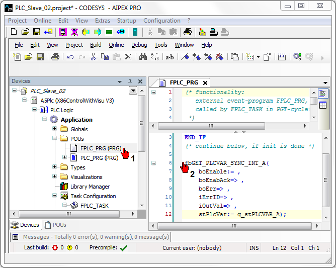
Instantiate in the real-time task FPLC_PRG a function block type GET_PLCVAR_SYNC_INT.
Link the function block variable 'stPlcVar' with the communication variable (g_stPLCVAR) .
Create message configuration for the EtherCAT slave
Click the AIPEX PRO menu 'Configuration ...' → 'Configuration create'
Communication settings
Siehe 'Creating PLC program and message configuration'.
Communication settings section
|
|
The icon of the mapped PLC communication variable is highlighted in 'green'. |
The configuration is finished! The program can be tested.
|
|
|
