Controller card KW-R07 / KW-R17 / KW-R27
Preparations
- If the controller card KW-R07 / KW-R17
- Connect your PC via point to point connection to the USB interface X235 or to the Ethernet interface X85 of the controller card.
Connect the compact inverter to the 24 VDC supply voltage.
Wait until the compact inverter is run-up.- LED H2 green continuous light: SBM (system ready message)
- LED H2 red continuous light: Error
- If LED H2 displays an error, you may read it with AIPEX PRO.
Start AIPEX PRO and log on to the drive. (See document Software description AIPEX PRO V3, Part no. 204979).
In the tab 'Diagnostics', you will see some error messages which are based on the new combination of compact inverter and controller card.
You may initially ignore these messages.
Log out and close AIPEX PRO. - Start the program ATF - AMK Tool Flasher
You will get information about the use of this software from the document Software description ATF - AMK Tool Flasher (Part no. 203771).
Implementation
(Example KW-R07)
1. step: selecting target hardware and firmware
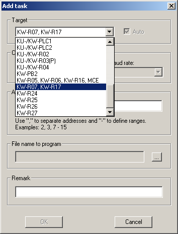
- Select 'Task' -> 'Add...'
- Select 'KW-R07, KW-R17' as target.
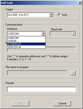
- With 'Communication', select an interface.
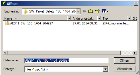
- With 'File name to program', select the firmware file AESF1_SW_105_1404_204927.zip.
- Confirm all entries with 'OK'
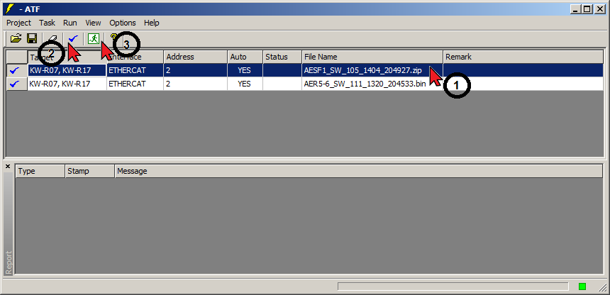
2. step: transferring the firmware to the controller card
- Select the task to flash by clicking into the respective line.
- Activate the task by clicking the button
 .
. - Start the update with
 .
.
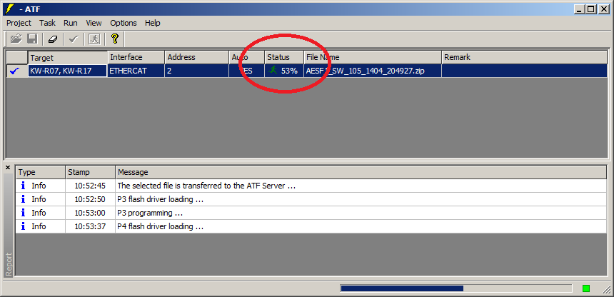
- During the flashing, the loading progress is displayed.
- Exit the ATF after the firmware was completely transferred.
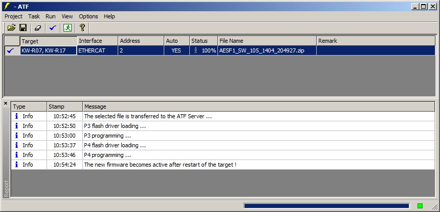
- Switch the controller off and on again. The new firmware will be activated.
|
|
If you want to flash the controller firmware, too, you can do it subsequently without switching the controller off. |

3. step: transferring the safe parameter set to the drive
- By installation of the new safety firmware, the check sum CRC of the safe parameter set becomes invalid.
When restarting the controller card, the LED H6 will stay off.
You will get the error message 3609 'Safety - Faulty parameter transfer' which can be read with AIPEX PRO.
- Parametrise the functional safety
- If there is an existing parameter set (file >drive_name<.blob):
Load this parameter set to the SafePMT, transfer it to the drive and validate it.
See documentSafety manual; functional safety, chapter startup, subtopic Parameterisation, Step 5 ff. - If you do not have access to the safe parameter set, newly parametrise the functional safety of the drive.
See documentSafety manual; functional safety, chapter Startup, subtopic Parameterisation.
- If there is an existing parameter set (file >drive_name<.blob):
- Generate the parameterisation report.
Completion
- Check the not safe drive parameters:
- If you got a backup file >drive_name<.aipex, transfer it to the drive by means of AIPEX PRO.
- If there is no existing parameter file, startup the drive as described in the document Initial startup KE/KW (Part no. 204539).
- If you connected your PC to the controller card via Ethernet interface, remove this connection and re-integrate the device to its network.
