|
*1 |
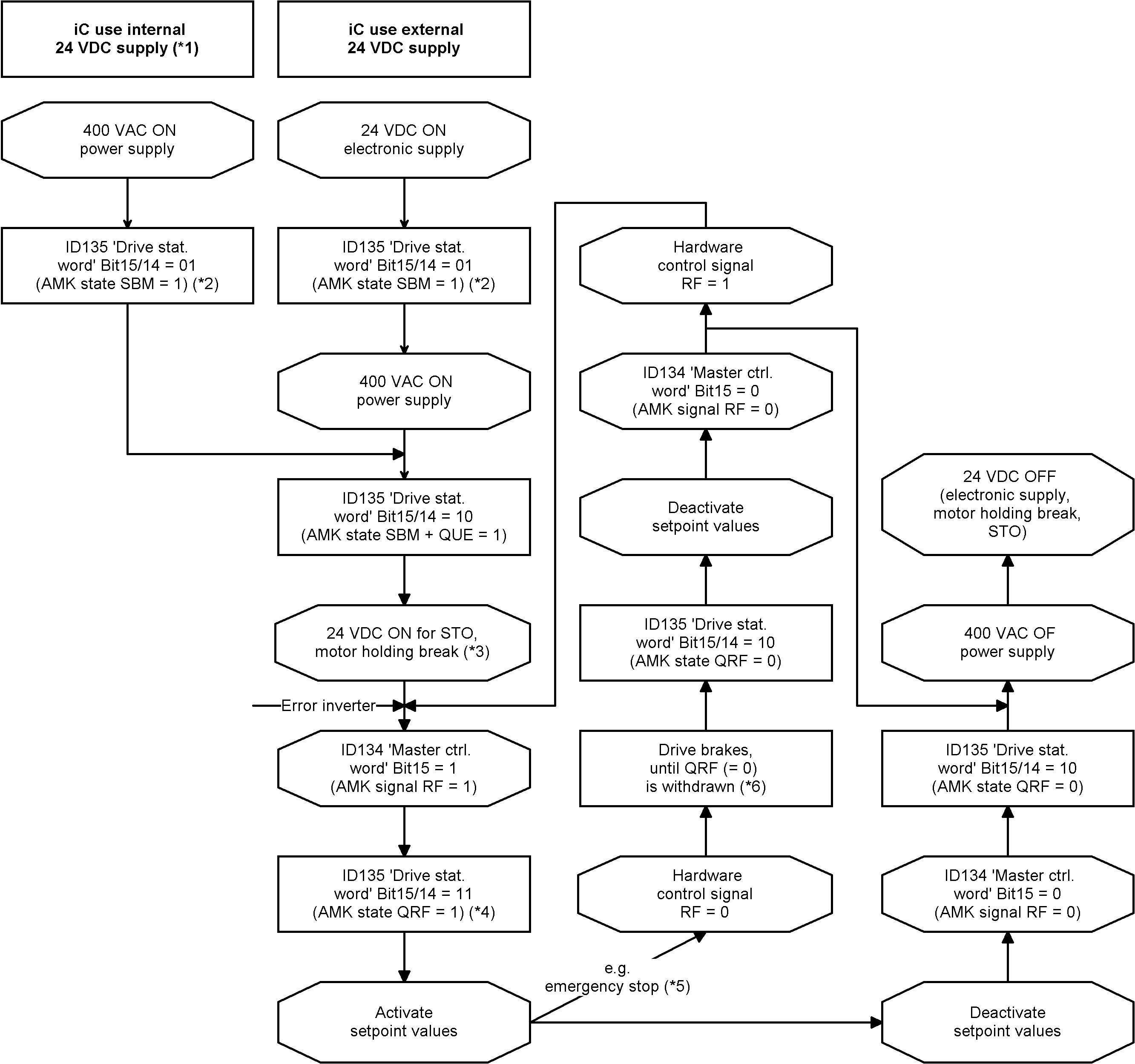
Hint limitations! After power on the internal 24 VDC supply is available after < 3 s. |
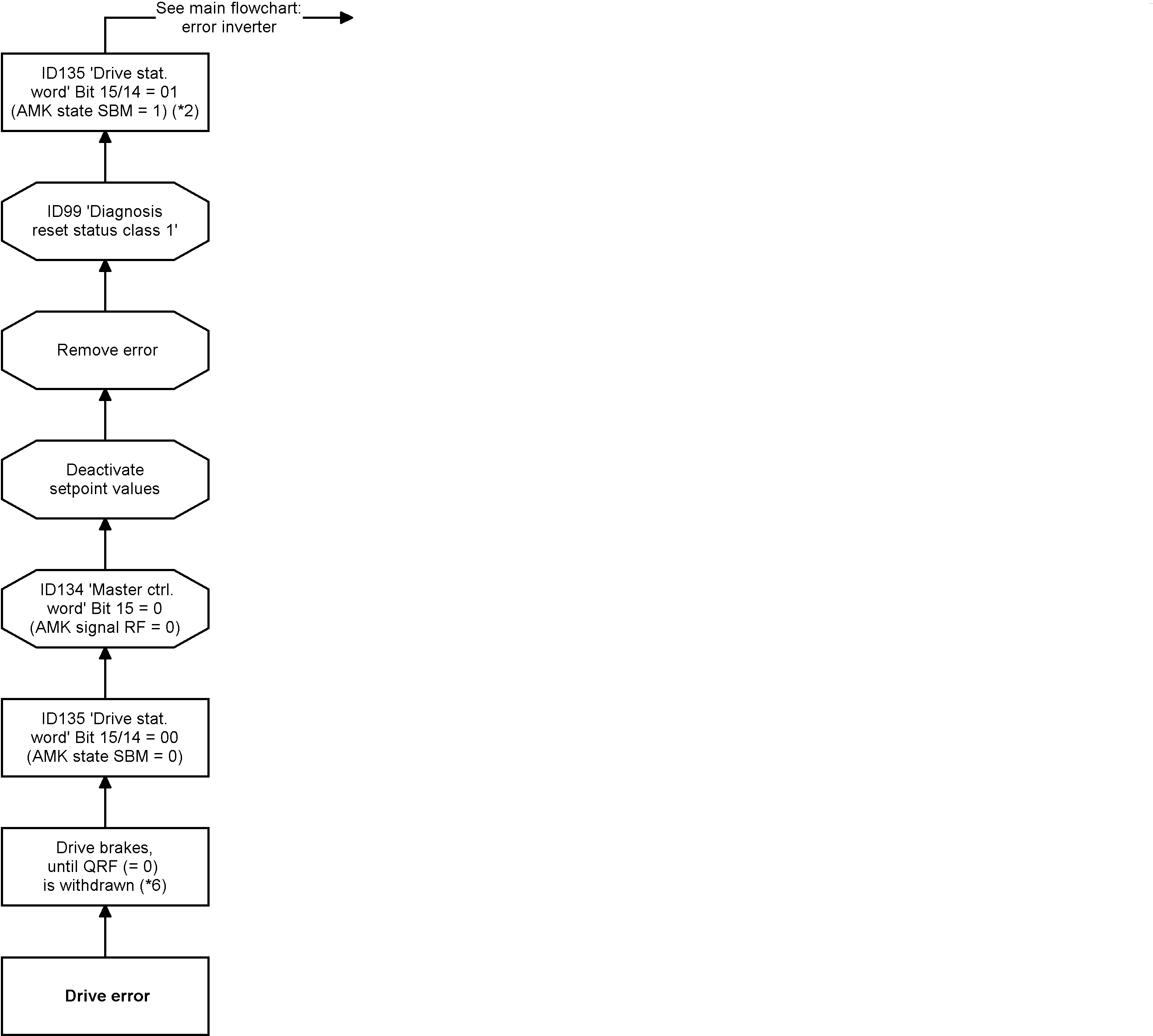
| *2 |
The module specific 'System ready' messages (SBM = 1) from the modules signal the error-free states. |
| *3 |
24 VDC supply must be applied at the latest at that time. Open / close motor holding brake will be automatically controlled trough the RF signal. |
| *4 |
Delay time until QRF is set depends on the connected motor resp. whether the data set must be newly calculated because of a modification of drive specific parameters. |
| *5 |
RF will be disabled via BE. BE is linked with PLC signal, see ID32796 'Source RF'. |
| *6 |
Motor is braked to a standstill after the ramp ID32782 'Deceleration ramp RF inactive'. |
|
*7 |
Pulse ≥ 1 ms. |
| *8 | (iC) Charging time after power on < 50 ms |
| *10 | Maximum 1 power on circuit per minute. |
