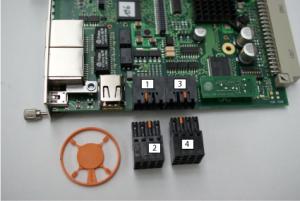
[X141] binary inputs and outputs and analog inputs
|
NOTICE |
|
|---|---|
| Material Damage! |
Material damage! A hardware defect will occur if the connections X141 and X132 are exchanged. Steps to prevent: |
Description
Use analogue input A1 to assign a torque or speed setpoint, depending on the selected operating mode.
The analogue input A2 limits the torque linear to the applied voltage if the function in the operating mode parameter ID32800ff is activated..
|
Input / output |
Port |
Parameter |
Code |
Meaning |
|---|---|---|---|---|
|
BI3 |
3 bit 2 |
ID32980 |
32905 |
NK (Cam signal) |
|
BO1 |
3 bit 0 |
ID32865 |
33031 |
QRF (Acknowledgement controller enable) |
|
BO2 |
3 bit 1 |
ID32866 |
33029 |
SBM (System ready message) |
Technical data
- Norm IEC 61131-2 type 3 digital inputs:
Rated input voltage 0-30 VDC, maximal input current at 30 VDC = 15 mA
Level 0-5 VDC: low, 11-30 VDC: high
Electrically delay of Ton = 3-8 µs, Toff = 48-57 µs - Norm IEC 61131-2 digital outputs:
Rated output voltage 24 VDC, rated output current maximal 0.5 A, short-circuit safe, electrically isolated, electrically delay of Ton 8-20 µs, Toff = 50-55 µs at 200 mA load
- Analog inputs
- Differential inputs, potential-bound
- Input voltage: ±10 VDC (maximum 12VDC)
- Resolution: 12 bit for ±10 VDC
- Scanning cycle 250 µs
|
|
The GND potential of the setpoint source may deviate in relation to the PE by a maximum of ±10 VDC. |
Design
|
Type |
Poles |
Class |
|---|---|---|
|
Connector with spring connection |
8 |
2-row pin strip, coded to position 2 |
Assignment
|
[X141] |
Connection |
Signal |
Description |
|---|---|---|---|
|
front view, device side
Picture name: ZCH_KW-R05_X132 |
1A |
BE3 |
Binary input 3, 24 VDC ± 15%, max. 10 mA, potential separated, e.g. probe input |
|
1B |
BGND |
Reference potential |
|
|
2A |
BA1 |
Binary output 1, 24 VDC, 100 mA, potential separated, permanently short-circuit safe |
|
|
2B |
BA2 |
Binary output 2, 24 VDC, 100 mA, potential separated, permanently short-circuit safe |
|
|
3A |
A1N |
Analog channel 1 not inverted, ±10 VDC, max. 10 mA |
|
|
3B |
A2N |
Analog channel 2 not inverted, ±10 VDC, max. 10 mA |
|
|
4A |
A1I |
Analog channel 1 inverted, ±10 VDC, max. 10 mA |
|
|
4B |
A2I |
Analog channel 2 inverted, ±10 VDC, max. 10 mA |
Connection:
|
Cable |
8 x 0.8 mm² (max.)/ AWG 18, shielded |
|
Shield connection |
Shield on on one side on the module housing |
|
Cable assembly |
Weidmüller socket connector, 8-pin, coded to position 3, AMK part no. 28759 |
Circuit principle:
|
Analog inputs |
Binary inputs and outputs |
|
|
|
|
|
|
Picture name: ZCH_KEKW_Analogeingaenge |
Picture name: KEKW_binäre_EA |


